

CTS is the first fundamental change to power cable fabrication and design in decades.
This power delivery technology was developed by Enertechnos.
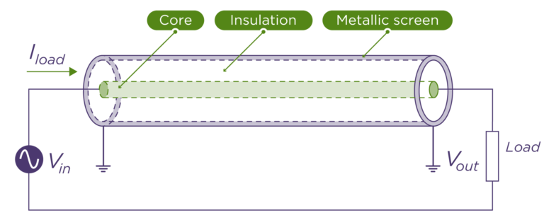
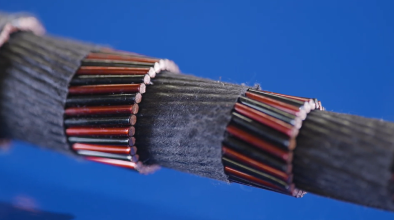
Capacitive Transfer System (CTS) is an innovative concept for power cable design. The new structure introduces a linear capacitor through the cable length, leading to lower losses and facilitating more power delivery than equivalent legacy cable systems.
Originally developed for electricity distribution networks, Enertechnos has refined CTS to be applicable in broader applications. These applications include offshore grids, wireless electric vehicle (EV) charging, aviation and other sectors. Find out more about the various applications here.
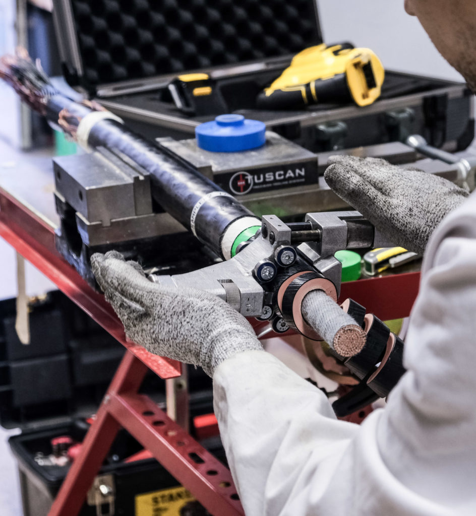
To minimise the risk of adoption for our solutions, we optimised CTS to be manufactured on conventional cable-making equipment, developed jointing methods and designed a cable protection system.
CTS is an innovative concept for power cables design, introducing a “linear capacitor” through the cable length, leading to lower losses and allowing delivery of more power than equivalent legacy cable systems.
Originally developed for electricity distribution networks, Enertechnos has refined CTS to be applicable in a wider area of applications, in offshore grids, wireless EV charging, aviation and other sectors.
To minimise the risk of adoption for our solutions, we optimised the design to be manufactured on conventional cable-making equipment; developed jointing methods; and designed a cable protection system.
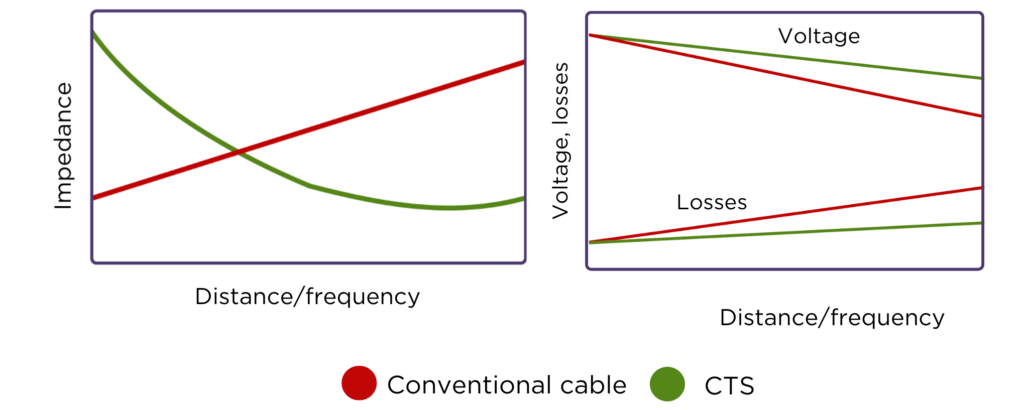
The system voltage and conductor impedance primarily define the power a cable can transmit. Impedance consists of two distance-dependant parameters: resistance and inductive reactance, which increase with the power frequency. As impedance increases with the distance, the cable can reach its limit, thus forcing users to go for higher voltages or thicker cables.
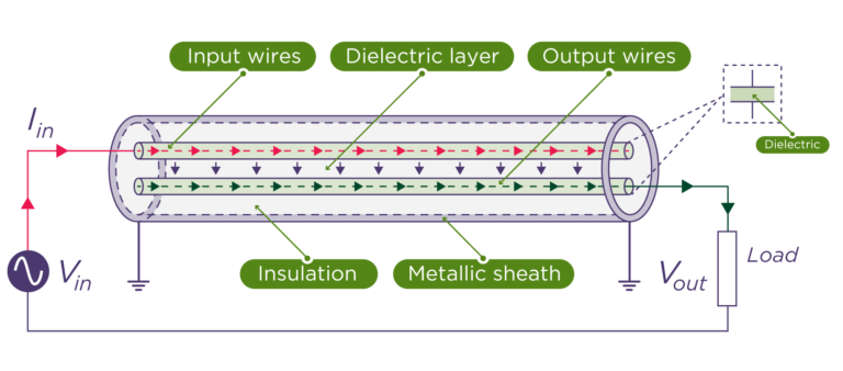
To combat this inductive reactance, the cable is designed to form its conductor into two electrodes along the entire length. One electrode is connected to the generator, and the other is connected to the load. In this way, the CTS cable acts as a capacitor offsetting most of the inductive reactance, leaving just shy of only the resistance part of the impedance.
Voltage drop between the generation and load is a limiting factor for how long the cable line can be.
With reduced voltage, a given load will draw greater current, which in turn increases energy losses. In medium-voltage and high-frequency cables, reactance is the key factor influencing the voltage drop.
By reducing impedance, CTS delivers power more efficiently across larger distances than conventional cable.
Voltage drop between the generation and load is a limiting factor for how long the cable line can be. With reduced voltage, a given load will draw greater current which in turn increases energy losses. In medium voltage and high-frequency cables reactance is the key factor influencing the voltage drop. CTS, by reducing impedance, delivers power more efficiently.
Skin effect is the tendency of a high-frequency alternating current to flow through only the outer layer of a conductor.
Skin effect means that losses, primarily through heating, increase with resistance. The innovative cable design of CTS allows for more evenly distributed current across the cable core, leading to an increased area conducting current, thus further reducing energy losses.
Losses, mostly through heating, increase with resistance and frequency due to skin effect. Innovative cable design with CTS allows for more evenly distributed current across the cable core, leading to increased area conducting current and further reducing energy losses.
Typically, when dealing with cables, capacitance is to be avoided, so why is CTS adding it?
The capacitance referred to in cable specifications is the capacitance between the core and the earth shield outside the cable’s insulation. This capacitance leads to current leaking to the earth and is detrimental to performance. The longer the cable, the worse this “shunt” capacitance problem becomes.
CTS capacitance is inside the core, and rather than leaking current, it is the means by which the current is delivered to the load. This means that the longer the cable, the higher the capacitance of a CTS cable and the more series capacitance it can supply.
Find out more about the advantages of CTS here.
Typically, when dealing with cables, capacitance is to be avoided, so why is CTS adding it? The capacitance referred to in cable specifications is the capacitance between the core and the earth shield outside the cable’s insulation. This capacitance leads to current leaking to earth and is detrimental to performance. The longer the cable the worse this “shunt” capacitance problem becomes. CTS capacitance is inside the core and rather than leaking current, it is the means by which the current is delivered to the load, so the longer the cable the higher the capacitance of a CTS cable and the more “series capacitance” it can supply.
| Cookie | Duration | Description |
|---|---|---|
| cookielawinfo-checbox-analytics | 11 months | This cookie is set by GDPR Cookie Consent plugin. The cookie is used to store the user consent for the cookies in the category "Analytics". |
| cookielawinfo-checbox-functional | 11 months | The cookie is set by GDPR cookie consent to record the user consent for the cookies in the category "Functional". |
| cookielawinfo-checbox-others | 11 months | This cookie is set by GDPR Cookie Consent plugin. The cookie is used to store the user consent for the cookies in the category "Other. |
| cookielawinfo-checkbox-necessary | 11 months | This cookie is set by GDPR Cookie Consent plugin. The cookies is used to store the user consent for the cookies in the category "Necessary". |
| cookielawinfo-checkbox-performance | 11 months | This cookie is set by GDPR Cookie Consent plugin. The cookie is used to store the user consent for the cookies in the category "Performance". |
| viewed_cookie_policy | 11 months | The cookie is set by the GDPR Cookie Consent plugin and is used to store whether or not user has consented to the use of cookies. It does not store any personal data. |